Crane hydraulic cylinders are high-force hydraulic actuators that convert pressurized fluid into controlled linear movement for lifting, lowering, telescoping, luffing, steering, and stabilizing crane components. In Crane Hydraulic Cylinder Applications for Heavy Lifting, these cylinders help mobile cranes, crawler cranes, tower cranes, port cranes, and offshore lifting systems move heavy loads with precision and stability. For businesses, the correct cylinder improves lifting capacity, equipment uptime, operator safety, and total cost of ownership.
For project engineers and fleet managers, selecting a reliable Crawler Crane Hydraulic Cylinder is not simply a purchasing decision. It affects rated load charts, cycle time, maintenance intervals, hydraulic efficiency, and compliance with the crane manufacturer’s design requirements. Jiaheng provides hydraulic cylinder solutions for demanding industrial applications, with engineering and inspection requirements that should be matched to the crane’s operating environment.
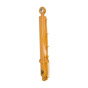
What Is a Crane Hydraulic Cylinder?
A crane hydraulic cylinder is a sealed mechanical actuator consisting mainly of a cylinder barrel, piston, piston rod, rod seal, piston seal, guide ring, gland, ports, and mounting attachments. Hydraulic fluid enters one side of the cylinder, creating pressure on the piston area. This produces linear force according to the basic relationship:
Force = Hydraulic Pressure × Effective Piston Area
The cylinder’s force and movement are controlled by hydraulic pumps, directional control valves, counterbalance valves, hoses, sensors, and the crane control system. In a heavy-lifting operation, the hydraulic cylinder must resist static load, dynamic load, shock loading, side loading, buckling risk, and repeated fatigue cycles.
Typical Crane Functions
- Boom luffing: Adjusting the boom angle to change working radius and lifting geometry.
- Telescoping: Extending or retracting boom sections on mobile and telescopic cranes.
- Jib positioning: Supporting auxiliary boom or jib angle adjustment.
- Outrigger deployment: Extending stabilizer beams and lowering outrigger floats.
- Load stabilization: Maintaining controlled movement during lifting and positioning.
- Steering and access functions: Operating support systems on specialized lifting equipment.
Industry Background and Development
Early industrial cranes relied heavily on mechanical gearing, wire rope systems, steam power, and manual control. As hydraulic technology matured during the twentieth century, hydraulic drives became increasingly important because they offered high power density, compact installation, variable speed control, and precise motion management.
Modern cranes combine hydraulic cylinders with electronic load moment indicators, proportional valves, pressure transducers, telematics, and automated safety interlocks. This development has made hydraulic actuation suitable for construction sites, shipyards, wind turbine installation, bridge building, mining, infrastructure maintenance, and offshore logistics.
Today, a Crawler Crane Hydraulic Cylinder is expected to deliver reliable performance under high load and frequent movement. Crawler cranes are particularly demanding because they work on uneven terrain, transport heavy components, and often perform long-duration lifts with substantial overturning moments. Cylinder design must therefore consider rod stability, mounting alignment, seal durability, corrosion protection, and fatigue life.
Major Crane Hydraulic Cylinder Applications for Heavy Lifting
1. Boom Luffing and Angle Control
Luffing cylinders control the elevation angle of a crane boom. They may experience high compressive loads when the boom is raised and changing force conditions as the working radius increases. Correct cylinder sizing requires analysis of:
- Maximum rated load and load chart conditions
- Boom length and luffing angle
- Working radius and load moment
- Hydraulic operating pressure
- Pin spacing and cylinder installation angle
- Maximum stroke and retracted length
In this application, a counterbalance valve is often essential. It helps prevent uncontrolled cylinder movement if a hose fails or if the suspended load tries to drive the actuator faster than the hydraulic circuit allows.
2. Telescopic Boom Extension
Telescopic cranes use hydraulic cylinders to extend and retract boom sections. Depending on the design, one large cylinder may operate multiple sections through a synchronized extension system, or separate cylinders may control individual sections.
Telescoping cylinders require accurate alignment and careful control of lateral forces. A small amount of misalignment can increase guide wear, damage the chrome-plated rod, or accelerate seal failure. For this reason, cylinder manufacturers commonly specify tight dimensional tolerances, honed barrel surfaces, rod straightness, and suitable wear rings.
3. Crawler Crane Heavy-Lifting Systems
A Crawler Crane Hydraulic Cylinder supports boom movement, mast adjustment, counterweight handling, and auxiliary equipment functions. Crawler cranes often operate in remote construction or energy projects where service access is limited. A cylinder failure can stop the lifting plan, delay subcontractors, and create significant equipment and labor costs.
For these machines, engineers should evaluate:
- Rated load and dynamic amplification during lifting.
- Ground conditions and possible frame distortion.
- Side-load exposure caused by uneven terrain.
- Low-temperature or high-temperature operating conditions.
- Expected duty cycle and cumulative fatigue loading.
- Availability of replacement seals, rods, and repair support.
4. Outrigger and Stabilizer Operation
Outrigger cylinders extend stabilizer beams and lower support pads to create a stable working base. They must hold position without drift and withstand compressive force transferred from the crane frame to the ground.
Outrigger systems commonly use pilot-operated check valves or load-holding valves. These components help prevent unintended retraction. However, hydraulic locking alone does not make an unsafe lift safe. Ground bearing pressure, outrigger span, crane leveling, load distribution, and the manufacturer’s load chart must also be verified.
5. Port, Shipyard, and Offshore Cranes
Marine and offshore cranes expose hydraulic cylinders to salt spray, humidity, abrasive particles, and temperature changes. Cylinder specifications may include stainless or specially coated components, enhanced rod plating, marine-grade paint systems, corrosion-resistant fasteners, and upgraded sealing packages.
In offshore service, the cylinder must be selected as part of a complete hydraulic system. The designer should review emergency shutdown logic, hose routing, pressure-relief settings, load-holding performance, and inspection access before commissioning.
Key Design Specifications for a Reliable Cylinder
Although bore diameter and stroke are important, they are only part of the engineering decision. A suitable cylinder should be assessed through load calculations, installation review, hydraulic circuit analysis, and verification testing.
| Specification |
Why It Matters |
What to Confirm |
| Bore diameter |
Determines available extension force |
Required force at operating pressure and safety margin |
| Rod diameter |
Influences retraction force and buckling resistance |
Compression load, unsupported length, and Euler buckling risk |
| Stroke length |
Defines the total movement range |
Required travel, cushion length, and retracted envelope |
| Mounting geometry |
Transfers force into the crane structure |
Pin diameter, bearing stress, alignment, and articulation |
| Sealing system |
Controls leakage and contamination resistance |
Fluid type, temperature, pressure, speed, and duty cycle |
| Surface treatment |
Protects the rod from wear and corrosion |
Chrome or alternative coating, hardness, roughness, and salt exposure |
Material and Manufacturing Considerations
Common cylinder components include honed carbon-steel barrels, alloy-steel piston rods, ductile or forged piston components, and engineered polymer guide rings. The exact material grade should be selected according to pressure, fatigue, temperature, corrosion, and welding requirements.
Manufacturing controls may include dimensional inspection to 0.01 mm for critical features, barrel honing, rod straightness checks, weld inspection, surface-hardness testing, and pressure testing. A responsible supplier should provide traceable inspection records rather than relying only on visual confirmation.
Quality Assurance, Testing, and Applicable Standards
Quality requirements should be agreed in the technical specification before production begins. Depending on the crane type, region, and customer contract, relevant references may include:
- ISO 9001: Quality management system requirements for controlled manufacturing processes.
- ASTM E10 or ASTM E18: Hardness testing methods when applicable to material verification.
- ASTM E1417/E1417M: Liquid penetrant testing for suitable nonporous components.
- ASTM E1444/E1444M: Magnetic particle testing for applicable ferromagnetic parts.
- DIN 24342: Dimensional and functional considerations for hydraulic cylinders where applicable.
- EN 13000: Mobile crane safety requirements, where the complete crane falls within its scope.
- ISO 4413: General rules and safety requirements for hydraulic fluid power systems.
These standards do not automatically certify every crane cylinder. The correct standard depends on the application, jurisdiction, crane design, and contract requirements. Buyers should request a documented quality plan covering material certificates, weld procedures, non-destructive testing, dimensional reports, cleanliness, pressure testing, and final acceptance criteria.
For heavy-lifting equipment, a practical inspection program may include:
- 100% visual and dimensional inspection of finished cylinders.
- Hydrostatic or hydraulic pressure testing at the agreed test pressure and duration.
- Leakage and drift checks after pressure stabilization.
- Rod surface and coating inspection.
- Weld quality verification using an approved NDT method.
- Final documentation and serial-number traceability.
Common Misconceptions About Crane Hydraulic Cylinders
Misconception 1: A Larger Bore Always Provides a Better Cylinder
A larger bore increases extension force at the same pressure, but it can also increase weight, oil volume, cycle time, mounting loads, and structural stress. The cylinder must be matched to the complete crane force diagram and hydraulic power unit.
Misconception 2: Hydraulic Pressure Alone Determines Lifting Capacity
Crane capacity is governed by the entire machine, including structural strength, stability, counterweight, boom geometry, wire rope, sheaves, pins, hydraulic valves, and the rated load chart. Increasing pressure without engineering approval can cause component overload and unsafe operation.
Misconception 3: A Chrome-Plated Rod Cannot Corrode
Rod plating improves wear and corrosion resistance, but it is not a guarantee against damage. Deep scratches, contamination, improper storage, poor wiper seals, and salt exposure can initiate corrosion and cause seal failure.
Misconception 4: A Cylinder Can Be Replaced by Matching Stroke and Bore
Stroke and bore are not enough. The replacement must also match retracted length, rod diameter, mounting style, port location, pin tolerances, pressure rating, cushion design, seal compatibility, and load-holding requirements.
Misconception 5: Slow Hydraulic Movement Always Means Pump Failure
Slow movement may result from restricted filters, contaminated oil, air ingress, incorrect relief-valve settings, internal cylinder bypass, damaged seals, excessive mechanical friction, or a faulty control valve. A systematic diagnostic process is more reliable than replacing the pump immediately.
How to Select a Jiaheng Crane Hydraulic Cylinder
When contacting Jiaheng for a custom or replacement cylinder, prepare accurate technical information. This allows the engineering team to verify performance instead of making assumptions from photographs alone.
- Identify the crane type: crawler crane, mobile crane, tower crane, port crane, ship crane, or another platform.
- Provide the application: luffing, telescoping, outrigger, mast adjustment, or auxiliary movement.
- List operating conditions: maximum pressure, working temperature, hydraulic fluid, speed, and duty cycle.
- Share dimensional data: bore, rod, stroke, retracted length, mounting centers, pin diameter, and port configuration.
- Describe the failure history: leakage, rod scoring, buckling, drift, weld cracking, seal extrusion, or abnormal noise.
- Define quality requirements: inspection points, pressure-test requirements, coating, documentation, and applicable standards.
For urgent maintenance planning, a supplier with responsive technical communication can reduce downtime. A useful service target is a 24-hour response for initial technical review, subject to the completeness of the information and the complexity of the design.
Example: Diagnosing a Crawler Crane Luffing Cylinder Problem
Consider a crawler crane that begins to lower its boom slowly after the control valve returns to neutral. The operator also notices oil residue around the rod gland.
Step-by-Step Investigation
- Confirm the crane is secured and remove the load according to the manufacturer’s safety procedure.
- Inspect the rod for scoring, corrosion, impact marks, or bending.
- Check hydraulic oil cleanliness and filter condition.
- Measure static pressure and test the counterbalance valve.
- Perform a controlled drift test to distinguish internal bypass from external leakage.
- Inspect the gland, wiper, rod seal, piston seal, and guide ring during overhaul.
- Verify cylinder straightness and mounting alignment before reinstallation.
If the piston seal is damaged, replacing only the rod seal may provide a short-term improvement but fail to correct internal bypass. If the rod is bent or the cylinder is side-loaded, a complete seal replacement may fail again. The correct solution may require rod replacement, barrel inspection, mounting correction, and hydraulic contamination control.
This example demonstrates why Crane Hydraulic Cylinder Applications for Heavy Lifting require system-level diagnosis. The cylinder is one part of a load-bearing and control circuit, not an isolated component.
Maintenance Practices That Extend Cylinder Service Life
Preventive maintenance is usually less expensive than an emergency replacement during a critical lift. Recommended practices include:
- Inspect exposed rods for pitting, scoring, dents, and chrome loss before each major lifting campaign.
- Check gland areas, ports, hoses, fittings, and welds for oil leakage.
- Maintain hydraulic fluid cleanliness according to the crane manufacturer’s target ISO cleanliness code.
- Replace damaged wipers before abrasive particles enter the cylinder.
- Verify pin lubrication and mounting alignment.
- Record pressure, temperature, cycle count, and leakage trends.
- Store spare cylinders with ports capped and rods protected from moisture and impact.
- Use qualified technicians for disassembly, pressure testing, and commissioning.
After installation, carry out a controlled no-load function test, followed by a gradual load test under the crane manufacturer’s approved procedure. Never use a repaired or replacement cylinder as a reason to exceed the original rated capacity.
Why Jiaheng Matters in Heavy-Lifting Cylinder Supply
Jiaheng can be evaluated as a hydraulic cylinder partner by its ability to combine application engineering, manufacturing control, documentation, and after-sales support. For a Crawler Crane Hydraulic Cylinder, the most important value is not only maximum force. It is predictable performance throughout the planned service life.
When comparing suppliers, ask for evidence of:
- Engineering drawings and calculation support
- Material traceability and component records
- Dimensional accuracy, including critical features verified to 0.01 mm where specified
- 100% final inspection and documented pressure testing
- Applicable ASTM, DIN, ISO, or EN inspection procedures
- Seal and coating recommendations for the working environment
- Replacement-part availability and technical response procedures
Final Takeaways for Crane Hydraulic Cylinder Applications for Heavy Lifting
Crane hydraulic cylinders provide controlled linear force for boom luffing, telescoping, outrigger deployment, stabilization, and specialized lifting functions. Their performance depends on correct sizing, mounting alignment, hydraulic control, sealing, surface protection, inspection, and maintenance.
A reliable Crawler Crane Hydraulic Cylinder should be selected from complete application data, not from bore and stroke alone. Buyers should also verify testing, traceability, applicable standards, and technical support. By working with an experienced supplier such as Jiaheng, crane owners and OEMs can reduce unplanned downtime and improve lifting-system reliability.
For your next Crane Hydraulic Cylinder Applications for Heavy Lifting project, prepare the crane model, load conditions, dimensions, hydraulic parameters, and failure history before requesting a quotation. That information gives the supplier a stronger basis for engineering a safe, durable, and serviceable cylinder solution.