A damaged hydraulic cylinder can stop an excavator, loader, press, lift, or agricultural machine in the middle of a workday. Choosing the wrong bore, stroke, mounting style, or pressure rating may cause leakage, slow movement, or early failure. This guide explains how to measure, select, install, bleed, and maintain Replacement Hydraulic Cylinders. It also covers replacement hydraulic cylinders for excavators, custom sizing, and the correct way to identify replacement hydraulic cylinders with mounting dimensions before ordering.
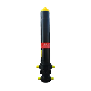
The bleeder valve is usually installed near the cylinder cap or rod end, but its exact position depends on the cylinder design. Always check the manufacturer’s drawing before opening a valve.
What Are Replacement Hydraulic Cylinders?
Replacement hydraulic cylinders are mechanical actuators designed to replace a worn, bent, leaking, or damaged cylinder in a hydraulic system. They convert hydraulic pressure into linear force and movement.
A typical cylinder includes:
- Cylinder barrel: The tube that holds pressurized hydraulic fluid
- Piston: Separates the two fluid chambers
- Piston rod: Transfers force to the machine linkage
- Rod seal and wiper: Keep fluid inside and dirt outside
- Piston seal: Prevents fluid from bypassing the piston
- End caps or gland: Close and support the cylinder
- Mounting points: Such as clevises, cross tubes, trunnions, or flanges
- Hydraulic ports: Allow oil to enter and leave the chambers
- Bleeder valve: Allows trapped air to escape during commissioning or service
The basic force calculation follows Pascal’s law:
[
F = P \times A
]
Where:
- F = cylinder force
- P = hydraulic pressure
- A = piston area
For example, a cylinder with a 50 mm bore has a piston area of approximately 1,963 mm². At 160 bar, the theoretical extension force is approximately:
[
16 \text{ MPa} \times 0.001963 \text{ m}^2 \approx 31.4 \text{ kN}
]
Actual force is lower because of seal friction, pressure losses, rod-side area, and system efficiency.
Common Industry Terms
| Term |
Meaning |
| Bore |
Inside diameter of the cylinder barrel |
| Stroke |
Maximum distance the piston rod travels |
| Rod diameter |
Diameter of the piston rod |
| Closed length |
Pin-to-pin length when fully retracted |
| Extended length |
Pin-to-pin length when fully extended |
| Working pressure |
Normal operating pressure |
| Test pressure |
Pressure used to verify cylinder strength |
| Double-acting cylinder |
Uses hydraulic pressure for both extension and retraction |
| Single-acting cylinder |
Uses hydraulic pressure in one direction and gravity or an external load in the other |
| Cushion |
A device that slows the piston near the end of its stroke |
| Bleeder valve |
A small valve used to remove trapped air |
Why Replacement Hydraulic Cylinders Matter
A hydraulic cylinder does more than push or pull. It controls load position, cycle timing, machine stability, and operator safety. A damaged cylinder may create several problems:
- Oil leakage around the rod
- Uneven or jerky movement
- Reduced lifting force
- Drifting while the control valve is neutral
- A bent rod or damaged mounting eye
- Contaminated hydraulic oil
- Excessive heat caused by internal leakage
- Unplanned machine downtime
Hydraulic systems often operate at pressures between 140 and 250 bar, although some industrial and mobile systems operate outside this range. At these pressures, even a small seal failure can release oil with enough energy to penetrate skin. The U.S. Occupational Safety and Health Administration recommends controlling hazardous energy during service under its lockout/tagout requirements, including OSHA 29 CFR 1910.147.
A replacement cylinder should therefore be treated as a load-bearing and pressure-bearing component, not as a simple tube-and-rod assembly.
Where Are Replacement Hydraulic Cylinders Used?
Replacement hydraulic cylinders are used in mobile equipment, industrial machinery, and material-handling systems.
Construction Equipment
Common applications include:
- Excavator boom, arm, and bucket cylinders
- Loader lift and tilt cylinders
- Bulldozer blade cylinders
- Crane stabilizer cylinders
- Dump truck hoist cylinders
- Concrete pump support cylinders
For excavators, the cylinder must match the original stroke, pin diameter, mounting width, hydraulic port position, and working pressure. A cylinder that fits the pin but has the wrong stroke can damage the machine linkage.
Agricultural Machinery
Farm equipment uses hydraulic cylinders for:
- Tractor three-point hitches
- Plow and cultivator adjustment
- Combine header movement
- Bale wrappers
- Seed drills
- Trailer tipping systems
- Sprayer boom folding
Agricultural cylinders often work in dusty and wet environments. A strong rod wiper and corrosion-resistant rod surface can reduce contamination entering the seal area.
Industrial Equipment
Industrial applications include:
- Hydraulic presses
- Injection molding machines
- Steel mill equipment
- Scissor lifts
- Conveyor tensioning systems
- Waste compactors
- Machine tools
- Automated production lines
In a press, cylinder alignment is especially important. Side loading can damage the rod, gland, and seals even when the rated pressure is not exceeded.
Marine and Offshore Equipment
Hydraulic cylinders are also found on:
- Ship steering systems
- Hatch covers
- Gangways
- Deck machinery
- Marine cranes
- Offshore handling systems
These applications may require stainless steel, nickel plating, special paint systems, or seals suitable for saltwater exposure.
How to Choose Replacement Hydraulic Cylinders
Selecting a replacement requires more than matching the outside appearance. Use the following process.
1. Identify the Original Cylinder
Record the information on the nameplate, drawing, or service manual:
- Manufacturer and model
- Bore size
- Rod diameter
- Stroke length
- Maximum working pressure
- Port thread type
- Mounting style
- Seal material
- Cushioning arrangement
If the label is missing, measure the cylinder directly.
2. Measure the Bore, Rod, and Stroke
Measure the following dimensions in millimeters:
- Bore: Measure the internal barrel diameter.
- Rod diameter: Measure the polished rod with a caliper.
- Stroke: Measure the difference between fully extended and fully retracted positions.
- Closed length: Measure from the center of one mounting point to the center of the other.
- Extended length: Repeat the measurement with the rod fully extended.
Do not estimate the stroke from the visible rod length. Some rod remains inside the gland when the cylinder is fully extended.
3. Check Mounting Dimensions
Mounting compatibility is critical. Confirm:
- Pin diameter
- Clevis width
- Cross-tube length
- Mounting hole spacing
- Flange dimensions
- Thread size
- Mounting angle
- Port orientation
Two cylinders may have the same bore and stroke but still be incompatible because their mounting eyes are offset by only a few millimeters.
4. Confirm Pressure and Load Requirements
The replacement cylinder must meet or exceed the machine’s working pressure. However, choosing a cylinder with a much larger bore is not always better.
A larger bore produces more force, but it also:
- Requires more hydraulic flow for the same speed
- Increases oil volume
- May overload the machine linkage
- Can slow the cylinder if the pump flow is unchanged
For example, increasing the bore from 50 mm to 63 mm increases piston area from about 1,963 mm² to 3,117 mm². At the same pressure, theoretical force rises by approximately 59%, but the required oil volume also increases by approximately 59% for the same stroke.
5. Select the Correct Seal Material
Common seal materials include:
- Nitrile rubber, or NBR: Common for mineral hydraulic oil and general temperatures
- Polyurethane, or PU: Good abrasion resistance in many mobile applications
- Fluorocarbon rubber, or FKM: Useful for higher-temperature or chemically demanding conditions
- Polytetrafluoroethylene, or PTFE: Often used for low-friction or high-temperature sealing designs
Seal selection must match the hydraulic fluid, operating temperature, pressure, speed, and contamination level. ISO 4413 provides general safety rules and requirements for hydraulic fluid power systems.
6. Select Rod Protection
The piston rod is exposed to moisture, dust, impact, and chemicals. Options may include:
- Hard-chrome-plated rod
- Induction-hardened rod
- Stainless-steel rod
- Nickel-chrome plating
- Protective rod cover
- Heavy-duty wiper seal
A rod with rust pits or deep scratches can damage the new seal within a short operating period. Repair the cause of rod damage before installing a replacement.
Custom Replacement Hydraulic Cylinders
Standard cylinders are useful when dimensions match an existing catalog model. Custom cylinders are often more suitable when the original design is obsolete or the machine has special requirements.
A custom hydraulic cylinder specification should include:
- Bore and rod diameter
- Stroke
- Retracted and extended length
- Working and test pressure
- Mounting type
- Port size and location
- Cushion requirements
- Seal material
- Rod coating
- Operating temperature
- Hydraulic fluid type
- Paint or corrosion protection
- Quantity and expected duty cycle
A manufacturer such as Jiaheng can use these details to review the design and recommend a suitable cylinder structure. For accurate production, provide photos, a dimension drawing, or the failed cylinder when possible.
How to Install Replacement Hydraulic Cylinders
Correct installation protects the cylinder and the machine.
Step 1: Make the Machine Safe
Before removing a cylinder:
- Park the machine on stable ground.
- Lower the attachment or support it with an approved mechanical support.
- Shut down the engine or power unit.
- Release stored hydraulic pressure.
- Apply lockout/tagout procedures where required.
- Clean the area around the hydraulic ports.
Never rely only on hydraulic pressure to hold a suspended load. Hydraulic valves can leak internally, and hoses can fail.
Step 2: Compare the New and Old Cylinders
Place the cylinders side by side and compare:
- Bore
- Rod diameter
- Stroke
- Pin and clevis dimensions
- Port position
- Cushion adjustment location
- Overall length
- Mounting orientation
Do not force a cylinder into position with a hydraulic control valve. If the pins do not align, correct the mechanical alignment first.
Step 3: Inspect Pins and Bushings
Worn pins and bushings can create side load. Check for:
- Oval holes
- Excessive clearance
- Cracks
- Uneven wear
- Missing retaining hardware
- Poor lubrication
A new cylinder installed on worn linkage may develop rod or seal damage even if the cylinder itself is correctly manufactured.
Step 4: Connect the Hydraulic Lines
Clean the hoses and fittings before connection. Keep protective caps on open ports until installation.
Check:
- Port thread type
- O-ring condition
- Hose routing
- Minimum bend radius
- Clamp position
- Potential contact with the rod or linkage
Do not use excessive thread sealant. Loose sealant can enter the hydraulic system and damage valves or seals.
Step 5: Start at Low Speed
After installation, operate the cylinder slowly through a partial cycle. Watch for:
- Oil leaks
- Jerky movement
- Abnormal noise
- Hose twisting
- Pin movement
- Rod misalignment
- Unexpected pressure rise
Do not place hands near a suspected leak. Use cardboard or a suitable leak-detection method instead of fingers.
Where Is the Bleeder Valve on a Hydraulic Cylinder?
The answer depends on the cylinder design. A bleeder valve may be located:
- On the cylinder cap
- Near the rod-end gland
- On the upper side of an end cover
- On a dedicated bleed port
- On the hydraulic circuit rather than on the cylinder itself
The valve is often positioned at a high point because air rises in hydraulic fluid. On some cylinders, there is no external bleeder valve. In that case, air is removed by slowly cycling the cylinder with the ports correctly connected.
How to Find the Bleeder Valve
Look for a small screw, needle valve, or capped fitting near the end cap. It is usually much smaller than the main hydraulic ports. Do not confuse it with:
- A cushion adjustment screw
- A pressure test port
- A grease fitting
- A hydraulic hose fitting
- A locking screw
Use the manufacturer’s drawing whenever possible. The image above shows the type of cylinder area where a bleeder valve may be found, but the exact position must be verified for the specific model.
How to Bleed a Hydraulic Cylinder
Use this general procedure only when the manufacturer permits it:
- Support the machine and remove people from the movement area.
- Fill the hydraulic reservoir to the correct level.
- Start the pump at low speed if possible.
- Open the bleeder slightly at the designated bleed point.
- Move the cylinder slowly through part of its stroke.
- Allow air and foamy fluid to escape.
- Close the valve when clear fluid flows without bubbles.
- Repeat on the opposite chamber if required.
- Check the reservoir level and add approved fluid.
- Cycle the cylinder several times at low speed.
- Inspect for leakage and confirm stable movement.
Hydraulic oil can be injected through the skin even when a leak appears small. Wear eye protection and follow the machine service manual.
Signs That a Replacement Hydraulic Cylinder Is Not Working Correctly
After installation, investigate these symptoms.
Jerky Movement
Possible causes include:
- Trapped air
- Contaminated oil
- Incorrect flow control setting
- Misalignment
- Damaged seal
- Low reservoir level
Bleeding may solve the problem when air is the cause, but repeated air entry suggests a leak on the suction side or another system fault.
Cylinder Drift
Drift can result from:
- Internal piston seal bypass
- Faulty control valve
- Load-holding valve leakage
- Hose failure
- Excessive load
- Thermal expansion of trapped fluid
A drift test should be performed according to the equipment manufacturer’s safety procedure.
External Oil Leakage
Check:
- Rod seal
- Static end-cap seals
- Hydraulic fittings
- Hose connections
- Welded joints
- Scratched rod surface
Tightening a fitting may not solve a leak if the thread or sealing surface is damaged.
Slow Operation
Slow movement may be caused by:
- Low pump flow
- Restricted hose or filter
- Incorrect cylinder size
- Excessive internal leakage
- Low engine or motor speed
- Oil with the wrong viscosity
- A partially closed valve
Do not assume that the cylinder is defective until system flow and pressure have been tested.
Maintenance Schedule for Replacement Hydraulic Cylinders
A simple inspection plan can prevent larger failures.
Before Each Shift
Check:
- Fresh oil around the rod
- Bent or scratched rod
- Loose pins
- Damaged hoses
- Abnormal noise
- Missing retaining clips
- Cylinder movement under load
Weekly or Every 50 Operating Hours
Depending on the machine manual:
- Lubricate pins and bushings
- Inspect rod wipers
- Check mounting bolts
- Clean dirt from the gland area
- Confirm reservoir level
- Inspect hydraulic filters and breathers
During Planned Service
Record:
- Operating hours
- Leakage rate
- Pressure readings
- Oil condition
- Rod surface condition
- Seal replacement history
- Any unusual temperature or noise
The exact service interval should follow the equipment manufacturer’s instructions and the working environment. Dust, water, shock loading, and high cycle rates require more frequent checks.
Quality Standards and Technical References
When comparing suppliers, ask how the cylinder is designed and tested. Useful references include:
- ISO 4413: Hydraulic fluid power—general rules and safety requirements for systems and components
- ISO 6020/2: Mounting dimensions for hydraulic cylinders used in certain industrial applications
- ISO 6022: Mounting dimensions for heavy-duty hydraulic cylinders
- SAE J517: Hydraulic hose and hose assemblies
- OSHA 29 CFR 1910.147: Control of hazardous energy during maintenance
- OSHA 29 CFR 1910.178: Safety requirements related to powered industrial trucks
These standards do not automatically mean that every cylinder is suitable for every machine. They provide a technical framework for dimensions, safety, and system design. The cylinder still must match the machine’s load, pressure, speed, environment, and mounting arrangement.
How to Choose a Replacement Hydraulic Cylinder Supplier
Before placing an order, ask the supplier for:
- A dimensional drawing
- Pressure rating
- Material information
- Seal specification
- Port and mounting details
- Inspection or test report
- Warranty terms
- Spare seal availability
- Production lead time
- Packaging and corrosion protection details
A supplier should be able to explain why the proposed bore, rod, seal, and mounting design suit the application. For unusual equipment, provide operating pressure, cycle frequency, maximum load, and environmental conditions.
Jiaheng can be considered when you need standard or custom hydraulic cylinders, especially when the original model is unavailable or the machine requires non-standard mounting dimensions.
Frequently Asked Questions
Can I replace a hydraulic cylinder with one that has the same stroke but a different bore?
Usually, this is not recommended without checking the system. A larger bore increases force and oil volume. A smaller bore reduces force and may create a safety problem. Verify pump flow, pressure, machine load, and mounting strength first.
How do I know if a hydraulic cylinder is the correct replacement?
Confirm the bore, rod diameter, stroke, closed length, extended length, mounting dimensions, port type, pressure rating, and seal compatibility. Matching only the outside length is not enough.
Why does my new hydraulic cylinder move unevenly?
Trapped air is a common reason, but the cause may also be low oil level, contaminated fluid, misalignment, restricted hoses, or a faulty control valve. Bleed the cylinder according to the service manual and inspect the complete circuit.
Is it safe to touch a hydraulic leak to find its location?
No. High-pressure oil can penetrate skin and cause a medical emergency. Use cardboard, wood, or an approved leak-detection method. Depressurize the system before repairing it.
Where is the bleeder valve on a hydraulic cylinder?
It is commonly found near the cap, rod-end gland, or another high point, but not every cylinder has one. Check the cylinder drawing and identify whether a small screw is a bleeder, cushion adjustment, or test port before opening it.
Should I replace the seals or buy a complete cylinder?
Seal replacement may be practical when the rod, barrel, piston, and mounting points are undamaged. A complete replacement is usually more suitable when the rod is bent, the barrel is scored, the mounting is cracked, or repair costs approach the price of a new unit.
What hydraulic fluid should I use?
Use the fluid specified by the machine manufacturer. Mineral hydraulic oil, biodegradable fluid, and fire-resistant fluid may require different seal materials. Do not mix fluids unless compatibility has been confirmed.
How long do replacement hydraulic cylinders last?
Service life depends on load, pressure, alignment, contamination, cycle count, rod protection, and maintenance. A cylinder operating within its rated conditions and supplied with clean, correctly filtered oil will generally last longer than one exposed to side loading or contaminated fluid.
Final Checklist Before Ordering
Use this checklist to reduce ordering errors:
- [ ] Bore measured
- [ ] Rod diameter measured
- [ ] Stroke confirmed
- [ ] Closed and extended lengths recorded
- [ ] Pin diameter checked
- [ ] Clevis or flange dimensions checked
- [ ] Port thread and position confirmed
- [ ] Working pressure verified
- [ ] Hydraulic fluid identified
- [ ] Seal material selected
- [ ] Rod coating selected
- [ ] Cushion requirement confirmed
- [ ] Bleeder valve location identified
- [ ] Installation and safety instructions reviewed
The next step is to compare your measurements with the original cylinder drawing and equipment service manual. If the dimensions are unusual, send photos and measurements to a qualified supplier such as Jiaheng for a technical review before ordering custom replacement hydraulic cylinders for excavators or other demanding equipment.