When I order Custom Hydraulic Cylinders, I do not begin by guessing a bore diameter or copying an existing model. I first define the required movement, force, pressure, installation envelope, and operating conditions. This guide shows how I calculate the correct stroke length and bore size, prepare a complete specification, and work with Jiaheng to reduce redesign, leakage, and delivery risks.
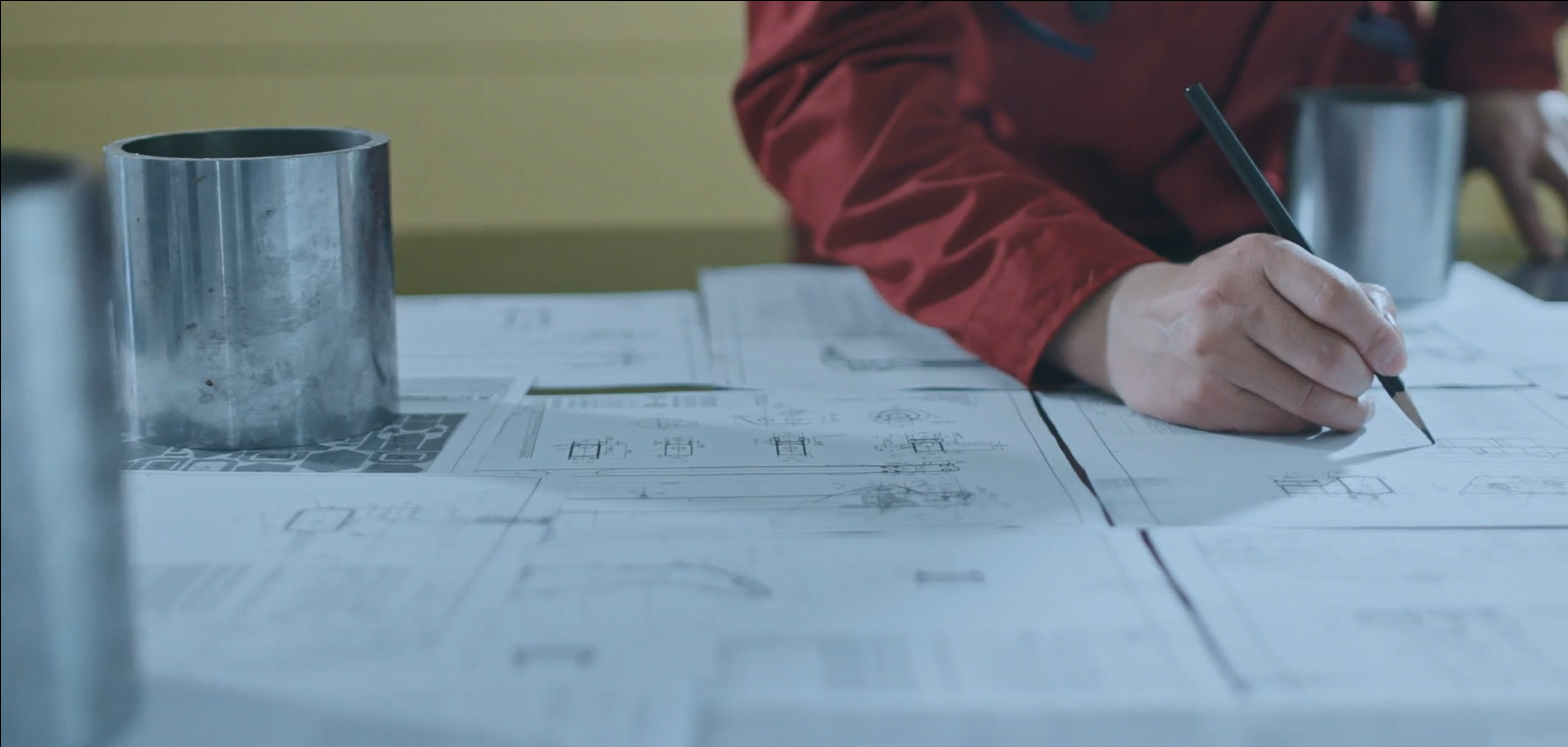
Start With the Application, Not the Cylinder
A hydraulic cylinder is a complete actuator system. Stroke and bore size depend on the machine load, speed, mounting geometry, hydraulic pressure, duty cycle, and environmental conditions.
Before requesting Custom Made Hydraulic Cylinders, I collect the following information:
- Application: press, tipper, agricultural equipment, material handling, construction machinery, or automation
- Required pushing and pulling force
- Maximum and minimum working pressure
- Desired cylinder speed
- Available installation length
- Required retracted and extended dimensions
- Load direction and side-load conditions
- Operating temperature and environment
- Required service life and duty cycle
- Rod-end and base-end mounting configuration
- Hydraulic port size and location
- Required seals, coatings, and corrosion resistance
This information prevents a common problem: selecting a cylinder that produces enough force but cannot physically fit or withstand buckling, side loading, or repeated cycling.
Step 1: Define the Required Stroke Length
Measure the Actual Machine Movement
The stroke is the distance the piston rod must travel between the fully retracted and fully extended positions.
I determine it by measuring the two attachment points:
[
\\text{Required stroke} = \\text{Maximum center-to-center distance} - \\text{Minimum center-to-center distance}
]
For example:
- Retracted pin-to-pin distance: 850 mm
- Extended pin-to-pin distance: 1,350 mm
- Calculated movement: 500 mm
The nominal cylinder stroke should be at least 500 mm. However, I also check whether the machine requires:
- A mechanical stop
- Cushioning before the end of travel
- Additional clearance
- A safety margin
- A position sensor or magnetic switch
- Rod-end thread engagement at both positions
In many applications, specifying exactly the measured movement can cause the cylinder to bottom out mechanically. A practical design may require a small allowance, such as 5–20 mm, depending on the linkage and end-stop arrangement. This allowance must be confirmed with the machine designer rather than added automatically.
Check the Retracted Length
Stroke alone is not enough. The retracted length determines whether the cylinder fits inside the machine.
The basic relationship is:
[
\\text{Extended length} = \\text{Retracted length} + \\text{Stroke}
]
When I send a drawing to Jiaheng, I include both center-to-center dimensions, not only “500 mm stroke.” I also specify the mounting type, such as:
- Clevis mount
- Trunnion mount
- Flange mount
- Foot mount
- Spherical eye
- Cross-tube mount
- Rod-end clevis
A spherical rod eye or spherical bearing may be necessary when the linkage creates angular misalignment. Without it, side loading can damage the rod, piston seal, and guide bush.
Step 2: Calculate the Required Bore Size
The cylinder bore controls the piston area and therefore the available hydraulic force.
Calculate Push Force
For extension, use the full piston area:
[
F_{\\text{extend}} = P \\times A
]
[
A = \\frac{\\pi D^2}{4}
]
Where:
- (F) = hydraulic force in newtons
- (P) = working pressure in pascals
- (A) = piston area in square meters
- (D) = bore diameter in meters
A useful metric formula is:
[
F(kN) = \\frac{P(bar) \\times \\pi \\times D^2(mm)}{40,000}
]
For a cylinder operating at 200 bar with a 100 mm bore:
[
F = \\frac{200 \\times 3.1416 \\times 100^2}{40,000}
]
The theoretical extension force is approximately 157 kN.
Calculate Retraction Force
Retraction force is lower because the rod occupies part of the piston area:
[
F_{\\text{retract}} = P \\times \\left(\\frac{\\pi D^2}{4} - \\frac{\\pi d^2}{4}\\right)
]
Where (d) is the rod diameter.
For a machine that must pull a load, I always calculate retraction force separately. Using only the extension force can result in an undersized cylinder.
Include a Design Factor
The theoretical force should not be treated as the working load limit. I account for:
- Friction in the linkage
- Pressure fluctuations
- Shock loading
- Acceleration and deceleration
- Uneven load distribution
- Seal friction
- Temperature-related viscosity changes
- Mechanical efficiency
A typical preliminary design factor may be between 1.25 and 1.5, but the correct value depends on the application risk and duty cycle.
For example, if the machine requires 80 kN of effective force and I use a 1.3 design factor:
[
F_{\\text{design}} = 80 \\times 1.3 = 104 kN
]
I then select a standard bore that exceeds this requirement at the actual working pressure.
Step 3: Select the Rod Diameter and Check Buckling
Bore size determines force, but rod diameter affects tensile strength, stability, and service life.
A larger bore with an undersized rod may produce sufficient force but fail under compression. I check rod buckling using the cylinder’s:
- Maximum unsupported length
- Mounting condition
- Load direction
- End restraint
- Rod material and yield strength
- Safety factor
- Compression load
For long-stroke Custom Made Hydraulic Cylinders, buckling analysis is essential. The correct rod diameter may require a stepped rod, larger guide length, or a different mounting arrangement.
I also check the rod slenderness ratio and use an engineering method such as Euler buckling analysis for idealized conditions. For real machinery, I ask the hydraulic cylinder manufacturer to validate the design against the actual pin-to-pin geometry.
Step 4: Confirm Pressure, Speed, and Flow
Bore and stroke must match the hydraulic system.
Flow Requirement
Cylinder speed is determined by flow and effective area:
[
Q = A \\times v
]
Where:
- (Q) = flow rate
- (A) = piston area
- (v) = rod speed
For a 100 mm bore cylinder extending at 0.1 m/s:
[
A = 0.00785 m^2
]
[
Q = 0.00785 \\times 0.1 = 0.000785 m^3/s
]
This is approximately 47 L/min.
During retraction, the annular area is smaller, so the same pump flow produces a higher rod speed. I calculate both extension and retraction speeds before finalizing the design.
Distinguish Working and Proof Pressure
The specification should clearly state:
- Rated working pressure
- Maximum peak pressure
- Proof or test pressure
- Relief valve setting
- Pressure fluctuation frequency
For example, a cylinder may operate at 210 bar but require a higher pressure test according to the agreed design and quality standard. I ask Jiaheng to identify the applicable test procedure rather than assuming that working pressure and test pressure are identical.
Step 5: Choose the Cylinder Construction
After calculating stroke and bore, I define the construction details.
Important Technical Specifications
| Specification |
Example |
| Cylinder type |
Double-acting hydraulic cylinder |
| Bore |
100 mm |
| Rod diameter |
56 mm |
| Stroke |
500 mm |
| Working pressure |
200 bar |
| Test pressure |
Confirm with supplier and design standard |
| Mounting |
Rear clevis and spherical rod eye |
| Port |
G1/2 or SAE, location specified on drawing |
| Rod material |
Hard-chromed induction-hardened steel |
| Barrel material |
Honed steel tube |
| Seal material |
PU, NBR, FKM, or application-specific compound |
| Cushioning |
Adjustable on extension and retraction |
| Environment |
Outdoor, dust, moisture, -20°C to +80°C |
| Inspection |
Dimensional, pressure, leakage, surface, and functional testing |
For Custom Hydraulic Cylinders, the seal package must match the fluid and temperature. Standard mineral oil service may use NBR or polyurethane seals, while high-temperature or chemically aggressive environments may require FKM or another specialized compound.
Step 6: Address Mounting and Side Load Conditions
Hydraulic cylinders should ideally apply force along their centerline. Side loading creates excessive wear on the guide bush, rod surface, and piston seal.
I verify:
- Pin alignment
- Parallelism between mounting points
- Angular movement during the stroke
- Linkage geometry
- Side loads at both end positions
- Required bearing clearance
- Available space for hose routing
If the cylinder cannot remain aligned, I specify spherical bearings, articulated mounts, or an external guide system. A cylinder should not be used as a structural guide unless it has been specifically designed for that purpose.
Step 7: Prepare a Complete RFQ for Jiaheng
A complete request allows Jiaheng to respond quickly and accurately. I include:
- Application description and photos
- A 2D drawing with all mounting dimensions
- Required stroke and retracted length
- Bore, rod diameter, and force requirements
- Working, peak, and test pressure
- Extension and retraction speed
- Hydraulic fluid and temperature range
- Mounting and port details
- Coating and corrosion requirements
- Quantity, packaging, and delivery destination
- Applicable standards and inspection requirements
I also specify dimensional tolerances. For example, critical dimensions may require accuracy to 0.01 mm, while non-critical welded dimensions may use a broader tolerance. The tolerance must be realistic for the manufacturing process and identified on the drawing.
A useful RFQ sentence is:
Please confirm the bore and rod selection, buckling safety factor, theoretical extension/retraction force, flow requirement, mounting dimensions, seal material, pressure-test procedure, and inspection report before production.
Quality Standards and Verification
To build confidence in Custom Made Hydraulic Cylinders, I request documented quality controls rather than relying only on a product photograph.
Depending on the application, relevant references may include:
- ISO 6020/2 for compact hydraulic cylinders
- ISO 6022 for heavy-duty hydraulic cylinders
- ISO 10100 for hydraulic fluid power cylinder acceptance testing
- ISO 2768 for general dimensional tolerances where applicable
- DIN or ISO surface-finish requirements for honed tubes and sealing surfaces
- ASTM B117 when salt-spray corrosion testing is required for coated components
The supplier and buyer should agree on the exact standard edition and acceptance criteria before production.
I may request:
- 100% pressure and leakage inspection
- Bore and rod dimensional inspection
- Surface roughness verification
- Weld visual inspection
- Material certificates
- Hardness testing
- Coating-thickness measurement
- Functional cycling
- Inspection report with serial numbers
For a critical production line, 100% inspection of pressure and leakage is more appropriate than sampling alone. Jiaheng can also be asked to confirm whether a quotation includes inspection records and a 24-hour technical response for engineering questions.
Common Problems and How to Solve Them
The Cylinder Produces Enough Force but Moves Too Slowly
This usually indicates insufficient pump flow, excessive restriction, or an oversized bore.
Solutions include:
- Verify actual pump flow under load
- Check valve and hose pressure drop
- Recalculate required speed
- Use a flow-control valve correctly
- Confirm whether a smaller bore is acceptable
The Rod Buckles During Extension
This can result from a long stroke, compressive loading, poor mounting, or side load.
Solutions include:
- Increase rod diameter
- Reduce unsupported length
- Add a center support
- Use a guided mechanism
- Change the mounting configuration
- Request a buckling calculation from Jiaheng
The Cylinder Leaks Prematurely
Premature leakage may be caused by contamination, rod damage, poor alignment, incorrect seal material, or excessive pressure spikes.
Solutions include:
- Improve filtration
- Protect the rod with a wiper and bellows where necessary
- Match seals to fluid and temperature
- Confirm rod surface finish and hardness
- Eliminate side load
- Check the relief-valve setting
The Cylinder Does Not Fit the Machine
This often happens when only the stroke is specified.
I prevent it by supplying:
- Retracted center-to-center length
- Extended center-to-center length
- Pin diameter
- Mounting width
- Port orientation
- Rod-end thread dimensions
- Clearance envelope
- Hose-bending radius
Tools That Improve Design Efficiency
I use the following resources before placing an order:
- A CAD drawing in DWG, DXF, or STEP format
- A hydraulic force and flow calculator
- A digital caliper and steel tape for field measurements
- A pressure gauge installed near the cylinder
- A laser alignment tool for mounting points
- A cylinder buckling calculator
- A tolerance checklist
- A service-life and cycle-count record
- Jiaheng’s engineering review and drawing approval process
A simple spreadsheet can calculate bore area, rod area, extension force, retraction force, speed, and flow in seconds. For production equipment, I keep the approved drawing and inspection report together with the machine maintenance documentation.
A Practical Specification Example
For a lifting application, my preliminary specification may look like this:
- Cylinder type: double-acting
- Required force: 80 kN pulling and pushing
- Working pressure: 200 bar
- Design factor: 1.3
- Required design force: 104 kN
- Stroke: 500 mm
- Retracted length: 850 mm
- Bore: selected to exceed 104 kN at 200 bar
- Rod: verified for buckling at the maximum compressed length
- Speed: 100 mm/s extension
- Fluid: ISO VG 46 hydraulic oil
- Temperature: -20°C to +80°C
- Mounting: spherical rear clevis and rod eye
- Inspection: 100% pressure and leakage testing
- Documentation: approved drawing, material certificates, and inspection report
Jiaheng can then review the assumptions and recommend the nearest standard bore and rod combination instead of manufacturing an unnecessarily expensive size.
Final Checklist Before Ordering From Jiaheng
Before approving Custom Made Hydraulic Cylinders, I confirm:
- [ ] Stroke is based on actual pin-to-pin movement
- [ ] Retracted and extended lengths are shown
- [ ] Extension and retraction forces are calculated separately
- [ ] Bore is selected using actual working pressure
- [ ] Rod diameter has passed a buckling review
- [ ] Side-load and alignment risks are addressed
- [ ] Speed and flow requirements are compatible
- [ ] Seal material matches the fluid and temperature
- [ ] Mounting, ports, threads, and clearances are dimensioned
- [ ] Applicable ISO, DIN, or ASTM requirements are documented
- [ ] Pressure and leakage inspection criteria are agreed
- [ ] The final drawing is approved before production
The most reliable way to specify Custom Hydraulic Cylinders is to combine the stroke measurement, force calculation, rod stability check, hydraulic-system data, and complete mounting drawing. By sending these details to Jiaheng, I reduce quotation delays, prevent installation problems, and improve cylinder service life. Start by measuring the two mounting positions, calculate the required force at real operating pressure, and request a formal engineering review before placing your order.